Home › Unlabelled ›
Instrument Cluster Connector Wiring Diagram 03 / Wiring Schematic For 2002 Gauge Cluster Ls1tech Camaro And Firebird Forum Discussion / Splice/wire/connector also shown on cb.
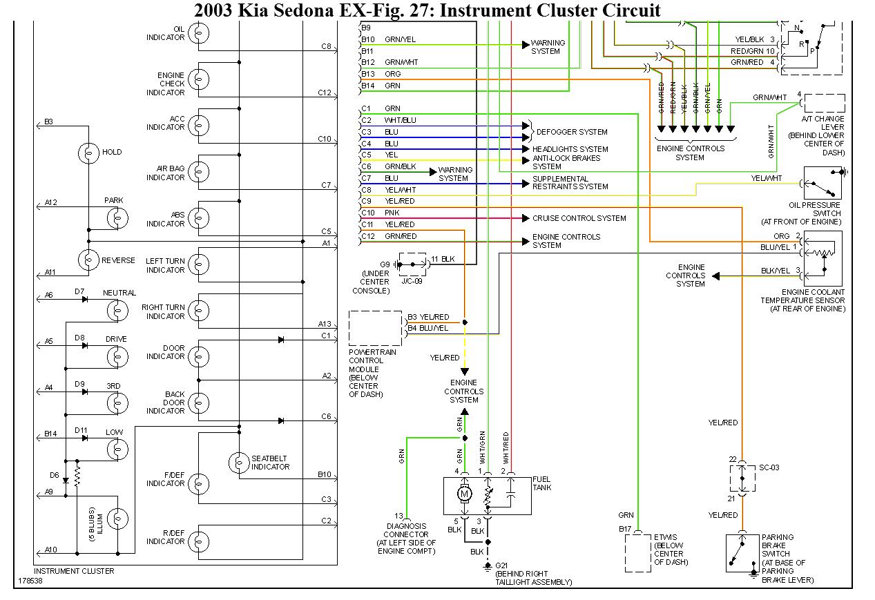
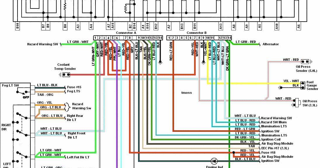
Instrument Cluster Connector Wiring Diagram 03 / Wiring Schematic For 2002 Gauge Cluster Ls1tech Camaro And Firebird Forum Discussion / Splice/wire/connector also shown on cb.. 15 pin connector has 13 colored wires like white with blue stripe i don't see this in the manual ? Identifying instrument cluster connector terminals courtesy of mitsubishi motor sales of america. Color code key instrument cluster instrument cluster instrument cluster brightness sensor left turn signal (fused) connector sleeve circuit 31 (4) cockpit connector sleeve). Wiring diagram instrument cluster pin hook up : The wiring diagrams are grouped into individual sections.
Need 12v and ground in the blue connector. Wiring diagram instrument cluster pin hook up : 1975 mercedes 450 wiring diagram instrument cluster pin hook up : The connector can be used for the battery, oil pressure temp (with new sender) and the speedometer. Make sure that the wire #3 on connector x10114 goes to the tach signal and it will work (verify the wiring diagram for your level of instrument cluster just to.
03 Kia Sedona Wiring Diagram Wiring Diagram Schema Miss Hide Miss Hide Atmosphereconcept It from www.2carpros.com Wiring diagram instrument cluster pin hook up : Looks like i need to move b6 to a7 on the saturn connector. Album other clusters have no brake warning lamp and the wire for that pin is missing (no connection). I would really appreciate it. Splice/wire/connector also shown on cb. I removed the instrument cluster, light switches, rear wiper switch, and all connections to the pcm. Does anyone have a more detailed wiring diagram then the haynes version? Make a wire 10 feet long with a cluster terminal on one end.
I'm in need of a wiring diagram for the main gauge cluster (should include the plug that goes into the back of the cluster) i had some wires pull out of the plug itself and need to find their proper homes.
1975 mercedes 450 wiring diagram instrument cluster pin hook up : These clusters may have electromechanical odometers or simple character displays. Our integrated circuits, reference designs and products. Aa power supply, circuit protection 1/4 3. I have a light bulb and light bulb. Usualy the wiring diagram for the vehicle shows the feeds to the instrument panel. It does mention a few wires only but i need them all. I have been looking for both diagrams for a year now. The wiring diagrams are grouped into individual sections. If testing indicates no mechanical or electrical failures, substitute ecu with 2: I'm in need of a wiring diagram for the main gauge cluster (should include the plug that goes into the back of the cluster) i had some wires pull out of the plug itself and need to find their proper homes. The tack hook up has to be taken off the pcm. The following must always be observed when replacing the instrument cluster
Color code key instrument cluster instrument cluster instrument cluster brightness sensor left turn signal (fused) connector sleeve circuit 31 (4) cockpit connector sleeve). The following must always be observed when replacing the instrument cluster Need 12v and ground in the blue connector. Wiring diagram instrument cluster pin hook up : Place it in the appropriate pin #26 on the green cluster connector.
Diagram Gmc Truck Instrument Cluster Wiring Diagram Power To Main Full Version Hd Quality To Main Bajawiring4 3forbusinessclub It from 4.bp.blogspot.com Would anyone out there happen to have the wiring diagram for the connector on the body control module? ▼ affix page 2 here ▼. I don't understand pin 5 of the cluster connector and the temperature light. Aa power supply, circuit protection 1/4 3. Place it in the appropriate pin #26 on the green cluster connector. I have been looking for both diagrams for a year now. Got k line in the green sorted. These clusters may have electromechanical odometers or simple character displays.
Problem is that it couldn't be found on any of the forums that i usually frequent and elsa didn't have it either.
Place it in the appropriate pin #26 on the green cluster connector. Hey friends, i need some wd to cluster for consumer power feeds terminals 15 and 30, grounds + fuses to 0x17 and 0x19 and pin outs for instrument cluster for this model if you search for and install elsawin, you will have all the wiring diagrams you need. Each solution combines a full suite of hardware and software tools, complemented by. Fingers crossed the instrument cluster can understand what the bcm is programmed to. Problem is that it couldn't be found on any of the forums that i usually frequent and elsa didn't have it either. I've seen a couple threads here and on other forums asking for the instrument cluster pinout and lately i needed it as well. The tack hook up has to be taken off the pcm. I don't understand pin 5 of the cluster connector and the temperature light. Splice/wire/connector also shown on cb. Apologize for hijacking your thread but has anyone swapped their 1990 instrument cluster for one out of a 1991 (or vice versa)? Got k line in the green sorted. I would really appreciate it. Download as pdf, txt or read online from scribd.
Problem is that it couldn't be found on any of the forums that i usually frequent and elsa didn't have it either. Album other clusters have no brake warning lamp and the wire for that pin is missing (no connection). Color code key instrument cluster instrument cluster instrument cluster brightness sensor left turn signal (fused) connector sleeve circuit 31 (4) cockpit connector sleeve). Download as pdf, txt or read online from scribd. If testing indicates no mechanical or electrical failures, substitute ecu with 2:
2006 Toyota Highlander Obd Connector Wiring Diagram Wiring Diagrams Star Site Star Site Alcuoredeldiabete It from static-assets.imageservice.cloud Looks like i need to move b6 to a7 on the saturn connector. 1975 mercedes 450 wiring diagram instrument cluster pin hook up : Aa power supply, circuit protection 1/4 3. A f20 batt cluster radio, b 15a. Each solution combines a full suite of hardware and software tools, complemented by. * wiring diagram * wiring harness instrument panel harness * cluster gauge the instrument panel harness uses this connector for the instrument panel (meter cluster): Hey friends, i need some wd to cluster for consumer power feeds terminals 15 and 30, grounds + fuses to 0x17 and 0x19 and pin outs for instrument cluster for this model if you search for and install elsawin, you will have all the wiring diagrams you need. Inspect ecu connectors and related wiring harness.
I have been looking for both diagrams for a year now.
The connector can be used for the battery, oil pressure temp (with new sender) and the speedometer. Wiring diagram instrument cluster pin hook up : Our integrated circuits, reference designs and products. Color code key instrument cluster instrument cluster instrument cluster brightness sensor left turn signal (fused) connector sleeve circuit 31 (4) cockpit connector sleeve). Does anyone have a more detailed wiring diagram then the haynes version? I don't understand pin 5 of the cluster connector and the temperature light. How does the automatic lighting (numbers) level adjustment work? Each solution combines a full suite of hardware and software tools, complemented by. Album other clusters have no brake warning lamp and the wire for that pin is missing (no connection). Need to make a bench harness. I removed the instrument cluster, light switches, rear wiper switch, and all connections to the pcm. The tack hook up has to be taken off the pcm. I have an instrument cluster with same printed circuit, and i wonder if anybody has a higher resolution image of question 2: